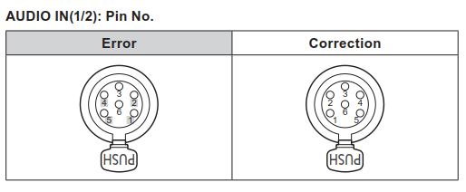
The description of pin assignment in the Operating Instruction is not correct. We apologize and will correct it. Operating Instruction (PDF): Page 120, Excerpted Version: Page 55 Connecting a microphone, etc. according to the incorrect description of pin assignment causes trouble such as no audio output or defective audio. (Meanwhile, this causes no damage to the microphone.)
August 2017 Updated
Was this helpful?
Additional feedback is welcome.
Thank you for your feedback.
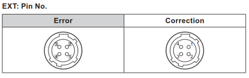
The description of pin assignment in the Operating Instruction is not correct. We apologize and will correct it. Operating Instruction (PDF): Page 120, Excerpted Version: Page 55 So the Washer control according to the incorrect description of pin assignment causes the pump to continue working all the time. As a result, trouble occurs such as a continuous spraying at first and then no water sprayed after a lapse of time. (Meanwhile, this causes no damage to the Washer device.)
It is a function to automatically adjust the picture level and color temperature in response to changes in the outdoors. And the items this function controls can be selected by setting the menu. AE mode: This controls Auto Exposure by controlling the gain, controlling the shutter and changing the ND filter when the adjustment cannot be done by controlling the iris only. AE+ATW mode: This automatically controls ATW in addition to the control of [AE].
September 2017 Updated
Was this helpful?
Additional feedback is welcome.
Thank you for your feedback.
It can be supplied from an external DC power supply (*1), a PoE++ hub (*2) or a PoE++ injector. (*1)<12V IN> XLR connector: Input 10.8 V - 21.6 V DC. (*2)Use a hub or an injector that supports PoE++ standard (IEEE802.3bt Draft ver. 2.0 compliant). *If the hub or injector does not meet the specifications, the status display lamp is lit in orange and such a device will not work. Make sure if your hub satisfies the specs. Or check the settings on your hub. * Operation-Verified PoE++ Injector P/No.: GV-PA901 (GeoVision Inc.)
September 2017 Updated
Was this helpful?
Additional feedback is welcome.
Thank you for your feedback.
The external DC power supply has priority. If both power supplies are connected at first and then the external DC power supply is disconnected, the camera will reboot automatically and its video image will be interrupted during the rebooting process. Also, if the external power supply is turned on while the power is being supplied from the PoE++ hub, the camera will reboot in the same way.
September 2017 Updated
Was this helpful?
Additional feedback is welcome.
Thank you for your feedback.
It has been verified that the following 3rd party devices can work with AW-HR140 camera. PoE++ Compliant Injector P/No.: GV-PA901 (GeoVision Inc.)
September 2017 Updated
Was this helpful?
Additional feedback is welcome.
Thank you for your feedback.
For connecting directly to a controller: Cross cable (category 5 or above, max. 100m) For connecting through a PoE++ hub: Straight cable (category 5e or above, max. 100m) For connecting through a normal (non-PoE++ compliant) hub: Straight cable (category 5 or above, max. 100m) For connecting via serial connection: Straight cable (category 5 or above, max. 1,000m)
September 2017 Updated
Was this helpful?
Additional feedback is welcome.
Thank you for your feedback.
For supported operating systems and web browsers, please refer to the page of “Computer Requirements” in Operating Instruction.
The camera cannot be controlled by an infrared remote control (AW-RM50). It does not have a mechanism to receive a signal from the infrared remote control (AW-RM50).
September 2017 Updated
Was this helpful?
Additional feedback is welcome.
Thank you for your feedback.
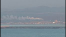
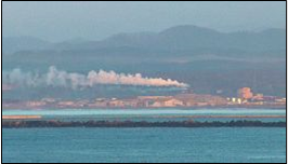
This is a compensation function to make images clearer when the camera is installed at a foggy place, etc. (You can select from three compensation levels.) > # Images are for illustrative purposes only
September 2017 Updated
Was this helpful?
Additional feedback is welcome.
Thank you for your feedback.
It is equipped as standard with the wiper, heater and defroster. But the washer unit is sold separately. The camera has the contact output for control of the washer unit. For further details, please refer to Operating Instructions [Installation Instructions provided].
September 2017 Updated
Was this helpful?
Additional feedback is welcome.
Thank you for your feedback.
It is for inputting external audio (line). When connecting a microphone or a device with a different level, adjust its level using an amp, etc. separately. (Specifications) Input impedance: High impedance Input: 2 channels, XLR balanced input Input level: +4dBu/0dBu/-20dBu (selectable in camera menu)
September 2017 Updated
Was this helpful?
Additional feedback is welcome.
Thank you for your feedback.
It is supported. A commercially available controller can be connected via RS-422 interface. # The camera is not equipped with a daisy-chain connection function. # Outdoor functions cannot be directly controlled using the controller. Control them by setting the camera menu. # For functions uncontrollable with the standard protocol, please refer to page 10 of Operating Instruction.
September 2017 Updated
Was this helpful?
Additional feedback is welcome.
Thank you for your feedback.
The status display lamp is on the connector panel of the camera’s back side. It lights up in the following ways depending on the status of the camera. Orange: When the unit is on standby (In this state, the video image is not output from the camera.) Green: When the power is on Red: When trouble has occurred in the unit
September 2017 Updated
Was this helpful?
Additional feedback is welcome.
Thank you for your feedback.
Up to 14 users can access it at the same time. However, depending on the setting for transmission bit rate or others, the number of users that can access it may be restricted.
September 2017 Updated
Was this helpful?
Additional feedback is welcome.
Thank you for your feedback.
They can be output at the same time.
September 2017 Updated
Was this helpful?
Additional feedback is welcome.
Thank you for your feedback.
It can be superimposed on SDI and IP at the same time.
September 2017 Updated
Was this helpful?
Additional feedback is welcome.
Thank you for your feedback.
Factory default settings are within the following range. If you set a random address, the 1st, 2nd and 3rd segments of IP address must be the same as those of default gateway setting. 【Factory Default】 IP address: 192.168.0.10 Subnet mask: 255.255.255.0 Default gateway: 192.168.0.1 # IP addresses that can be used are 192.168.0.2 - 192.168.0.254. 【Examples: Random Settings】 IP address: 192.168.2.20 Subnet mask: 255.255.255.0 Default gateway: 192.168.2.1 # IP addresses that can be used are 192.168.2.2 - 192.168.2.254.
September 2017 Updated
Was this helpful?
Additional feedback is welcome.
Thank you for your feedback.
According to the way of being installed, the camera needs an alteration in advance, which is the change of positions of pins at the camera’s mechanism end point. If these pin positions do not match the installation way, the movable range (left and right) of pan head is narrowed and that causes a malfunction. Change the positions of pins at the mechanism end point according to the camera’s way of installation. For details, please refer to the following Manual 【AW-HR140-Turning Output Image Upside Down】. AW-HR140-Turning Output Image Upside Down
September 2017 Updated
Was this helpful?
Additional feedback is welcome.
Thank you for your feedback.
According to the way of being installed, the camera needs changing the positions of pins at its mechanism end point as well as changing the camera menu setting. For details, please refer to the following Manual 【AW-HR140-Turning Output Image Upside Down】. AW-HR140-Turning Output Image Upside Down
September 2017 Updated
Was this helpful?
Additional feedback is welcome.
Thank you for your feedback.
It is possible. When AW-HR140 camera is switched to [Standby mode], its current pan, tilt, zoom, focus and iris values (*) are stored in the memory. (POWER ON Preset function) (*)Focus and iris values can be stored only when they are set manually. Adjust the pan, tilt and zoom to your desired angle of view, and then switch the camera’s power to [Standby mode] using the controller. Next time you turn on the power, POWER ON Preset function will work to adjust the pan, tilt and zoom to the angle of view stored in the memory when having been switched to Standby mode. So, if you always use the controller to switch the power to [Standby mode], never fail to set your desired angle of view every time before switching to [Standby mode]. If the power supply is cut off by the external power source, etc., the angle of view you specify is not stored. So, next time you turn on the power, the camera recalls the angle stored at the time of previous switchover to [Standby mode].
September 2017 Updated
Was this helpful?
Additional feedback is welcome.
Thank you for your feedback.
Camera Menu: System > Others > Other2/5 > Focus Mode ⇒ Select [Manual]. *Default: [Auto] # AW-RP50/AW-RP120 controller operation: Press “FOCUS AUTO” button on the front panel of AW-RP50/AW-RP120 controller to turn off this button’s light. Manual control will be enabled. When Focus Mode is [Manual], you can change the setting for “Focus ADJ With PTZ”. *What is “Focus ADJ With PTZ”? It is a function to compensate for out-of-focusing when the subject goes out of focus during panning, tilting and zooming. If you completely take the manual control of focus, set this setting to [Off]. *Default: [Off]
September 2017 Updated
Was this helpful?
Additional feedback is welcome.
Thank you for your feedback.
Camera Menu: Camera > Brightness > Brightness1/2 > Iris Mode ⇒ Select [Manual]. *Default: [Auto] # AW-RP50/AW-RP120 controller operation: Press “IRIS AUTO” button on the front panel of AW-RP50/AW-RP120 controller to turn off this button’s light. Manual control will be enabled.
September 2017 Updated
Was this helpful?
Additional feedback is welcome.
Thank you for your feedback.
The camera’s OSD (on-screen menu) can be displayed on SDI1 output only.
September 2017 Updated
Was this helpful?
Additional feedback is welcome.
Thank you for your feedback.
It is not possible. Extender Zoom works within the range of optical zoom.
September 2017 Updated
Was this helpful?
Additional feedback is welcome.
Thank you for your feedback.
You can use Preset Scope setting to select the items to be recalled when calling up a preset memory. Camera Menu > System > Other > Other1/4 > Preset Scope ⇒ [Mode A / B / C] *Default: [Mode A] Mode A: Pan, Tilt, Zoom (including Digital Zoom), Focus, Iris, Gain, White Balance adjustment value Mode B: Pan, Tilt, Zoom (including Digital Zoom), Focus, Iris Mode C: Pan, Tilt, Zoom (including Digital Zoom), Focus # Operation from AW-RP50 controller: MENU > [9] SETUP > [5] PRESET > 3.Scope ⇒ [Mode A / B / C] # Operation from AW-RP120 controller: [MEM SETTIN] button > SCOPE ⇒ [MODE A / B / C]
September 2017 Updated
Was this helpful?
Additional feedback is welcome.
Thank you for your feedback.
By registering users and setting up the authentication settings on the user management screen of Web setup screen, you can restrict users that can access the camera from personal computers and mobile terminals. If you access the Web screen after setting up the authentication settings, the authentication screen for user name and password is displayed so that only the authorized users can access the camera. # In order to ensure security, the password for the user name of “admin” must be changed without fail. It is also recommended that the password should be changed at regular intervals. (Procedure for Setting) (1) Log in to the Web setup screen [Setup]. (2) Click the [User auth.] tab of the user management screen [User mng.]. (3) Select [On] at [User auth.] item for user authentication setting. Then press [Set] button to determine the setting. By setting up this setting, only the registered users are allowed to access the camera. (Procedure for Registering a New User *Up to 18 users can be registered.) # Input the user name and password, and select the access level (*1). Then press [Set] button to determine the settings. # You can view registered users by opening the pull-down menu for User Check. * A registered user is indicated in the form of “Registered user name [Access level]”. * To delete a registered user, select the user to be deleted and click [Delete] button at the right. (* 1)About Access Level You can select the user access level from the following. [1]Administrator ・・・ All the camera operations are allowed for the user at this level. [2]Camera control ・・・ Screen display and camera operations are allowed. Setting the camera settings is not allowed. [3]Live only ・・・ Only the display of Live screen is allowed. The camera operations and settings are not allowed.
September 2017 Updated
Was this helpful?
Additional feedback is welcome.
Thank you for your feedback.
Possible causes of not displaying [H.264] option on the web browser’s Live screen are as follows. Please check your camera’s settings or PC environment. H.264 transmission setting (whether to transmit H.264 images or not) is [Off]. *Default: [On] Mac (Safari) is being used. [H.264] image display capability can be used only with Windows Internet Explorer (*1). If your personal computer is Mac, [H.264] is not displayed. It only displays [JPEG]. (*1)In Operating Instructions, Windows marks are put for descriptions of the features that can be used only with Windows. For further details, please refer to Operating Instructions of each model. Incompatible web browsers like Google Chrome, etc. are being used. [H.264] image display capability can be used only with Windows Internet Explorer. *For supported operating systems and web browsers, please refer to the page of “Computer Requirements” in Operating Instruction. On mobile terminals like iPad or others, [H.264] images are not displayed. They only display [JPEG].