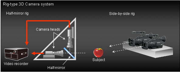
 3D BASICS Issue#2 Acquiring 3D video with AG-3DA1 As introduced in the previous issue (#1), the AG-3DA1 3D camera recorder makes it possible to produce natural 3D images by acquiring stereo images with the integrated twin-lens system. This issue introduces the principles of the twin-lens system and how 3D video works. Acquisition style of 3D video The most conventional way to create a 3D camera system is to use two video cameras or camera heads placed side-by-side, approximately 6.5cm (2.5 in.) apart, to capture images from slightly different angles for the left and right eyes.
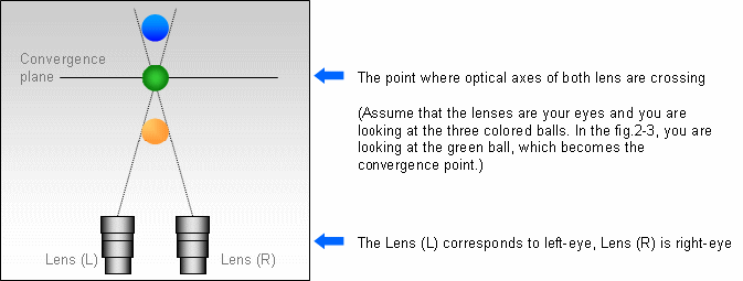
Figure 2-1 Conventional 3D camera system Advantages of the integrated 3D camera In the AG-3DA1 twin-lens camera, a camera head, and a memory card recorder are incorporated into a single, compact body. Unlike large 3D camera systems, this camcorder allows video shooting with greater mobility and from all angles, significantly reducing the time required for set up and adjustments, leaving more time for creative activities. Acquiring 3D video with AG-3DA1 : using an integrated twin-lens system When we look at objects, the line of sight of each eye cross at a certain point. Camera lenses operate on the same principle. The crossing point is called the “convergence plane” and the level of 3D effect (the extent to which objects appear to be in front of or behind the screen) can be controlled by varying the convergence plane. In 3D creation with the AG-3DA1, natural 3D images can be acquired with the built-in fixed inter-ocular twin-lens system. Also, the level of the 3D effect be adjusted by adjusting the position of the convergence plane. 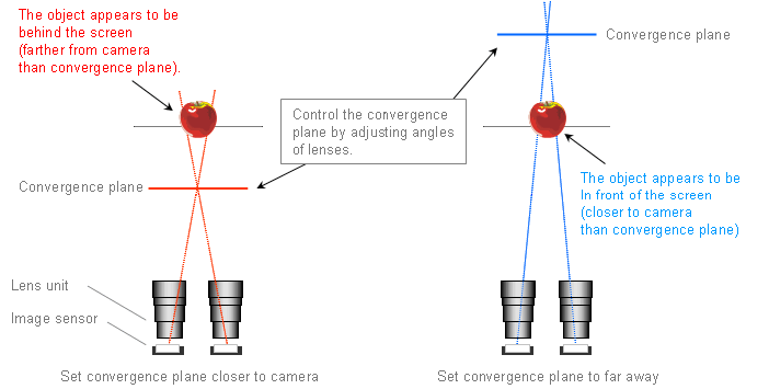
Depth and convergence plane: CASE A, convergence plane is set in between the objects. In the fig.2-3, the lines of sight of the two lenses are crossing at the green ball (this crossing point is the convergence plane) and the orange ball is closer to camera than the convergence plane, while the blue ball is farther from the camera than the convergence plane.
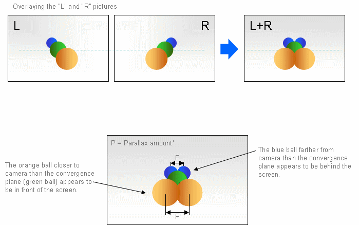
Figure 2-3 Fig.2-4 shows each perspective from the lens “L” (left-eye) and “R” (right-eye)
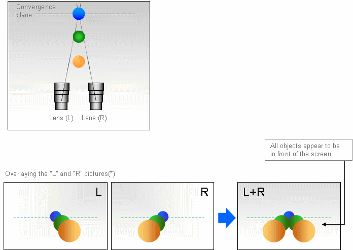
When people look at something, they receive slightly different images with different angle from their left and right eyes. The difference is called “Parallax” or “Binocular parallax” and it’s the amount of difference is called “Parallax amount”. When the images are formed into a single image by the brain, this parallax causes the appearance of spatial depth and the appearance of the solidity. The extent of the depth (how much objects appear to be in front of or behind the screen) becomes greater when the parallax amount increases. Depth and convergence plane: CASE B, All objects are closer to camera than convergence plane All objects appear to be in front of the screen as shown in the figure 2-6.
|
||||
